To split a string from the left and right of a phrase using a set of characters in the middle, you can use the combination of LEFT and RIGHT functions along with FIND function in Excel. Here is an example formula using your example string:
TheLEFTfunction returns the leftmost characters of a string up to a specified position. In this case, we are using FIND function to locate the first occurrence of ” – ” in the string, then subtracting 1 from the result to exclude the space before the hyphen.
The RIGHTfunction returns the rightmost characters of a string up to a specified position. In this case, we are subtracting the position of the first occurrence of ” – ” in the string from the total length of the string and subtracting 2 to exclude the space and hyphen.
Note that in the formulas above, A1 refers to the cell that contains the original string. You can adjust the cell reference as needed.
I usually use an additional monitor when using Revit. When I do, I usually move a lot of Revit interface elements to another screen. Including the Properties Palette and the Project Browser.
But when I work outside, I only can use 1 monitor. I need to rearrange my layout to work conveniently. Trust me; it’s not easy to dock the palettes as we want.
Don’t forget to change the USERNAME and Revit version to match yours.
Save a copy of this file to restore the layout to the current state. You can replace the file with your backup later.
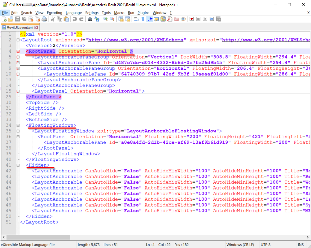
What’s in the RevitUILayout.xml file?
It’s an XML code. If you don’t know about XML, I suggest you leave it. Just save the file as a backup.
Basically, there are 3 groups of settings. The docked windows, floating windows, and the hidden windows. You can see there are several hidden palettes with this setting.
Revit will update this file after you make a change in the Revit UI and close Revit. The next time you open Revit, it will use the last setting in this file.
To Sum Up
Revit uses a different file to save the UI layout. If you get convenient with your current UI you better keep a backup so you can restore it later.
Saving different settings for Revit UI also useful when you need to work with a different setup. For example, using two or one monitors.
To reset Revit, you can just delete the Revit.ini file and a new one will be created the next time you open Revit. Remeber to close Revit before deleting the file. The “fresh” file is copied from this location:
C:\ProgramData\Autodesk\RVT 2020\UserDataCache
When creating a Revit deployment, which is an install with all the options pre-selected, you can select a custom Revit.ini file. This lets you set the default paths for templates, content, DWG import ligheweights and more, so everyone in the firm starts with the same settings.
Learn to create a 3D Revit tree with CAD-like 2D plan and elevation detail symbols. This tree’s 2D symbols will scale as you change its 3D height & radius.
Hate duplicating Revit family types just to make some trees bigger? Getting sick of their dull look? Wish you could change their radius and height independently from each other? Stop dreaming; we have the only Revit tree family you will need (most of the time)!
This tutorial will show how to create this smart tree so you can:
Change tree height and radius independently from one another using instance parameters. No more endless lists of identical tree types!
Show in different levels of detail distinctive tree annotation, from blobs to detailed components. A 3-for-1 bargain indeed!
Use any tree plan and elevation symbols of your choice. Once integrated properly, they will scale with the tree and help bring your drawings to life!
Choose to render either the tree’s family geometry or RPC appearance simply by changing the view’s level of detail. Make it as symbolic or realistic as you like!
Our smart tree family will have the below key attributes:
Category
Planting. Your current Visibility & Graphic settings or tree schedules will continue to work.
File size
2.15 Mb, tiny for a 3-in-1 tree with DWG-like annotation!
Available parameters
Tree HeightCrown Height, Radius & MaterialTrunk Radius & MaterialCardboard Tree Material (show only in shaded mode. Realistic or Ray Trace mode will show the RPC render appearance of the cardboard tree).
Levels of detail
At Coarse: Show tree elevations as 3D solids.At Medium: Show the Revit cardboard 3D tree which can be rendered.At Fine: Show custom 2D tree elevations of your choice.At all levels of detail: Show a custom tree plan symbol in floor plans.
STEP 1: FIND YOUR FAVOURITE 2D TREE PLAN AND ELEVATION SYMBOLS
Yes, you heard it right. Pick any tree annotation blocks of your choice. We can use up to 2 tree elevations, one for the Front/Back view and one for the Left/Right view.
For this tutorial, we picked our favourite blocks from the AutoCAD library and exported each to a separate DWG. If yours is in another format, make sure to convert that to DWG first.
STEP 2: CREATE 2D TREE ANNOTATION FAMILIES FOR REVIT
For each custom tree plan or elevation, create 1 new Revit planting family.
Import the tree plan or elevation DWG and place it in a Floor Plan or Elevation, respectively.
STEP 3: NEST 2D PLAN & ELEVATION TREE ANNOTATION FAMILIES INTO A NEW REVIT PLANTING FAMILY
Create a new Planting family using the same Revit template. Save it as “Tree Base”.
Load each of the newly created tree annotation family into “Tree Base”, essentially turning them into a “nested” entities.
When placing the nested family in “Tree Base”, do so in a plan view where the 2 default reference planes meet.
STEP 4: SET UP 2D REVIT TREE PRESENTATIONS AT MEDIUM AND FINE LEVELS OF DETAIL
Select 2 nested tree elevation families and change their Visibility Settings as below:
This way, they will show only at the Fine level of detail. At Medium, we will show the Revit default cardboard tree so that the tree can be rendered to RPC:
STEP 5: NEST THE COMBINED REVIT PLANTING FAMILY INTO A GENERIC MODEL FAMILY
Create a new Generic Model family and name it “Placeholder”:
Then, nest the Planting family into this new Generic Model family:
STEP 6: NEST THE GENERIC MODEL FAMILY INTO A FINAL REVIT PLANTING FAMILY
At this point, we have a Generic Model family. It now needs to be nested into a new Planting family called “Tree with instance Radius parameter” to have the complete family reported under the correct category:
Next, create in this final family new parameters for tree crown radius . Link these to those with the same name from the nested Generic Model family.
STEP 7: CREATE 3D REVIT TREE PRESENTATION FOR THE COARSE LEVEL OF DETAIL
If you still remember, we have set up our tree’s 3D appearance at Medium and Fine levels of detail. For Coarse, we will simply show the tree crown as an elliptical solid revolve and its trunk as a cylindrical solid extrusion. To aid setting constraints on these 2 new solids, create 2 reference planes to control their positions:
Create the tree crown using a solid revolve:
For the tree trunk, simply create an extrusion with a circular profile and top and bottom faces locked to appropriate reference planes. Create a new parameter called “Trunk Radius” here to control its size.
SHOW TIME!
Load the complete family into a new Revit project and let it shine!
Try to change the tree’s radius which will flex independently from its height:
The tree’s height, in turn, can be updated without affecting its Radius:
Change the level of detail to Medium and see the good all cardboard tree!
We keep it so that the tree can still be rendered. Switch the view mode to realistic to confirm:
Anyway, the tree is best shown at the Fine level of detail. Perfect for an artistic impression!
If you want a different tree plan or elevation symbols, simply return to step 2 and replace the imported DWGs.
What do you hear, most frequently along with the term BIM? I mostly hear that BIM design generates savings, eliminates collisions and improves the design process. At the same time, what are the challenges for designers working with BIM technology? I hear from them that projects are getting bigger and bigger, more and more complicated, […]
The pros of the data-based design process represent a reaction to the cons of model-driven design:
Files size – thanks to the fact that we do not need to keep all attributes in objects, files are much smaller.
Information management – database workflow opportunities are the same as with Excel. Filtering, searching, sorting rows and columns is simple and fast.
A single source of truth – all information starts with an entry in the database which determines the truth. And thanks to the background synchronization with modeling programs, we may easily transfer the data between those two sources.
Validation – having all the investor’s requirements, designed data and connected model in one place, we can efficiently perform requirement vs. design control.
Redesign – due to the possibility to perform control at an early stage of design in the database itself, or only in attributes, introducing modifications take less time. Of course, the relationship between cost of modifications and progress of the project does not alter – the later the modification is made, the more expensive and more difficult it is to implement.
We can check the progress of the whole project through an easy insight into the progress of the data.
Unfortunately, Data Driven Design does not solve all the obstacles faced by participants of large projects:
The design process differs from that known by designers and investors. Without being open to changes and the will to learn a new workflow and mindset, the data-based design will only be another tool and burden for all parties.
The need to rewrite the investor’s requirements from descriptive documents to metadata – currently, documents and Excel tables continue to prevail among investors. Introducing and structuring the information requires time and is subject to the risk of error.
Starting with the design process for the first time, we must be prepared to adapt standard databases to our requirements and create a strategy as well as modify the information flow if necessary.
Additional costs for the project – it is not a solution available from the Revit or another tool. If we prefer a dedicated solution, there is the cost of a license or purchase of the appropriate plug-in. To lower the entry barrier, you can stay with Excel and have (or create yourself) a script for Dynamo or Grasshopper.
Summary
In the first post starting Data Driven Design series, we introduced two different approaches to design. You have already discovered the pros and cons. Hence, if you are interested in Data Driven Design methodology, I invite you to the next posts, where I will discuss in detail the following issues: how should the database and the information management strategy on the project look like. I will also introduce specific project cases for various participants of the investment project.
Burning a gallon of gasoline produces 20 lbs of CO2 . An ICEV rated at 27 mpg produces 11 tons of CO2 over the course of 30,000 miles.
Yes. Manufacturing the 80 kwh Li-ion battery in a Tesla Model 3 Long Range produces about 13 tons of CO2. That’s offset by a couple of tons by not having the engine, transmission, exhaust system, gas tank, drive shaft, differential, and accessories needed in a comparable ICEV, so we’re talking about about 11 additional tons of CO2 released into the atmosphere when making a Tesla Model 3 over, say, the Audi A4 which is roughly comparable in size, weight, and performance.
However, driving a Tesla produces almost no additional CO2 when the battery is recharged from a renewable energy source (e.g., solar). At an EPA 27 mpg combined for the Audi producing 20 lbs of CO2/gal of gas consumed, break even is reached after about 30,000 miles.
Of course, few people today will charge an EV battery completely from a renewable energy source, so depending on where you live, the break even point will be higher. Worst case (100% coal fired electricity generation at 2 lbs of CO2 per kwh of electricity produced), the break even point jumps to 53,000 miles.
From break even, worst case, the Tesla produces only half the CO2 as does the Audi, and virtually none best case.
Over the life of each car (a conservative 150,000 miles), Audi A4 produces from 20 to 45 tons of CO2 more than does the Tesla Model 3. And that’s not even counting other harmful emissions from ICEV tail pipes.
When you have a non-orthogonal building model in Revit, you often need to create sections (or elevations) at various angles other than orthogonal. Normally you would want sections to be perpendicular/parallel to the angled model elements – the image above shows a section somewhat off parallel (much exaggerated version of a typical example where it may be slightly off).
If the section is notexactlyperpendicular (or parallel) to objects in the model you can encounter some very frustrating problems:
You may not be able to dimension sectioned elements
2D Symbolic lines in families may not show up (eg. door swing in elevation)
If you try to rotate the section to make itexactlyperpendicular (or parallel) to objects in the model, it is not as easy as you might expect:
One thing to avoid is measuring an angle and then typing in the measured angle during the rotate process – it is never accurate enough, even if you use several decimal points. Revit is extremely fussy about this – even a difference in angle of 0.000001 degrees may be enough to play havoc with dimensions and symbolic lines.
It is much more accurate to rotate by snapping start and end rotation points to the section to be rotated and some other reference element. The other problem you will encounter is an inability to snap to section lines.
Workaround
The trick here is two preparatory steps
Create a reference plane snapped to the section tail end, and exactly parallel to the angled wall
temporarily turn off the section markers at the ends of the section line – use the little cycle symbols et each end of the section. Then you can accurately snap to the section line when rotating.
To rotate the section:
During the rotate command, snap the centre of rotation to the point where the reference plane and section tail end meet (they must meet exactly)
Snap the start of the rotation to the section head end
Snap the end of the rotation to the other end of the reference plane
The section should end upexactlyperpendicular (or parallel) to objects in the model. Unfortunately the annotation on the section will have moved (much exaggerated in this example), so you may need to do some tidy up, and replacement of dimensions.
Don’t forget to turn the section head/tail marker back on.
You should now be able to dimension to sectioned elements, and the 2D symbolic lines in families should now be visible.
It is your call as to whether it is worth rotating the section line or just create a new section – it all depends on how much annotation there is, and how often the section has been referenced in other views.
Once you have the section oriented exactly right, you surely don’t want to lose it, so most likely you will pin it in place. Revit is very annoying in that you cannot change the 2D extents of a pinned section (as you can with datums like grids). Wouldn’t it be nice to be able to pin a rotated section and have it never move again, but still be able to adjust its 2D extents per view, without unpinning it. If you would like that, please go to the Revit Ideas forum and vote for ‘Allow us to change 2D extents of pinned sections‘
[Edit: Now we have a new way to do this in Revit 2019.1, which has an ‘Align Section’ functionality, using the existing ‘Align’ command. ]